|
Quite obviously, it can be seen that fitting an injected
engine into a non injected car means one of two things; either you convert the engine to
carburettors, or you convert the car to accept the Alfa original equipment injection
system. Another option is available, and that is to set the engine up so that it can
accept either carbs or aftermarket fuel injection. More on that later. But first lets have
the discussion.
Option 1 is to fit carburettors to the engine. To do this will involve physically
modifying the 16v intake manifolds in such a way that the 40 IDF carburettors can be
bolted on and the twin carburettor linkage modified in conjunction to work with them. You
will also have to fit and aftermarket electrical fuel pump capable of delivering
sufficient fuel to the carburettors, and fit the necessary wiring for that.
Modifying the inlet manifolds is not a task to be taken on lightly. Effectively what is
involved is fabricating a plate that had the IDF carburettor pattern and mounting points
for the linkage, then welding it on to the top of the 16v manifolds. You must also weld up
the holes into which the injectors go on the manifolds. All of this must then be hand
worked with rotary files and hand tools, so that the air passage shape is correct, and
there is no excess metal that fouls any other components. You must also ensure that the
top and bottom faces are flat enough to not cause gasket problems.
Almost invariably you will have to shorten the throttle linkage cross-shaft to suit.
However, simply cutting this in half, then removing the overlap and silver soldering a
suitable tight fitting piece of tube over the join will be adequate.
The advantage of this method is that you can keep your carburettors (and if you have them,
aftermarket filters), reuse your throttle linkage, existing fuel lines, it is simple, and
most rolling roads can sort out your jetting and setup.
The disadvantage is the cost is high, plus the fact that carburettors will not make the
best of the engine. Those fancy manifolds will cost lots of money to make, and you will
spend quite a bit on re-jetting your carburettors and settings will use up a lot of roller
time. The carbs will never match injection for smoothness and low down torque, and well
set up the injection could give better power, using less fuel to do it. Carbs will give
you a headache at Mot emissions time, too.
Option 2. The alternative is to use the standard injection and manifold setup. This will
mean no manifold problems, and the throttle bodies that the 16v come with are quite simple
in design, and will accept the standard filter box and air flow meter. It will give
smoother, better power, more economy, better throttle response, less problems with
emissions at MoT time, and will require no rolling road time due to the settings be preset
for that engine.
On the down side, it means that very little is available in the way of fine tuning. In
addition you will have to wire in a very complicated electronic system, you will have to
completely re-plumb the fuel lines, and fuel rails, a fuel pressure regulator is
necessary, and an electric high pressure fuel pump and high pressure filter will have to
be installed. Not for the faint hearted.
My solution to the fuel and ignition system problem
Having just told you that the carburettor option is
expensive, and the fuel injection solution is complicated, you would be forgiven for
thinking me an idiot to actually take a route which combines both of these.
Many companies like Jenvey, Weber, Lumenition all produce throttle bodies which are
basically modeled around the old carburettors. They are nothing but tubes with butterfly
valves in them, like carburettors, but instead of having jets, chokes, auxiliary venturis,
air corrector jets, emulsion tubes, floats and all that nausea, they just have a boss on
the side you stick an injector in. The injectors are standard size, the tubes are arranged
on IDF and DCOE Weber manifold patterns, with standard spacing.
These throttle bodies are then used in conjunction with a combined injection and ignition
engine management system (EMS). This uses several inputs;
Water temperature sensor
Air temperature sensor
Throttle position sensor
Crank angle / position sensor
Crank speed sensor
Using these inputs, the EMS is then able to look at RPM, throttle demand, water
temperature and air temperature to calculate exactly how much fuel is required, and
exactly when to ignite it for maximum effect, giving the best torque for any given speed.
As speed (RPM) multiplied by torque equals power, you can see that it also will maximise
the possible power. In addition to this, no choke will be required for cold starting, as
the EMS will automatically compensate for a cold engine.
The advantages of these throttle bodies are that they normally offer a straighter shot
into the ports for the fuel and air, which aids higher RPM power. The injector placement
is relatively close to the intake valve head, which aids torque. The throttle bodies can
be slightly larger than the equivalent carburettor as well, without losing much in the way
of low down torque. Carburettors are unable to provide a smooth, finely atomised,
accurately metered supply of petrol at low speeds due to low airspeed and therefore low
signal strength to the main jets. In order to give good torque with carburettors, you need
small diameter chokes, which then become restrictive at high RPM. Injection means accurate
metering and a very fine mixture distribution at low speeds irrespective of air speed, so
you can open up the diameter a little. In addition to all this, for the same power,
injection normally gives a slight improvement in economy at the top end, and vastly better
around town, and due to better torque spread makes it easier to drive.
A good example of the difference that they can make was demonstrated during a Car and Car
Conversions magazine back to back test using a Vauxhall / Opel 2.0 16 valve engine with
some minor cam changes. With a pair of 48 DCOE Weber carbs, it reached a best of 213 bhp,
and with throttle body injection reached up to 229 bhp. But that does not tell the whole
story - the carbs could not be jetted accurately enough with one set of jets and emulsion
tubes to give the correct fuel slope that the engine required. To get around this for the
test, they used a combination or settings which cheated (their words, not mine) the power
curve until it looked reasonable. This would have meant that to get the 213 bhp with
carbs, the owner would have to put up with a spluttering pig of an engine until he got to
about 4,000 RPM, and his fuel economy would have been poor. If he wanted reasonable
driveability, he would have had to sacrifice top end power. They proved the difference,
because with the injection they found nearly 40 bhp more at about 4,500 rpm over the
carbs. And they did it with less fuel. Basically the injection allowed them to get the
absolute best out of the engine at every point.
The disadvantages are that it is costly, and is going to be time consuming and
complicated, but no-one ever said I was sensible.
So my reasoning was this: The engine could be run using carburettors and distributor
ignition to ensure that it ran, that the installation was ok, that the linkages were
satisfactory and that nothing untoward was happening. It would also allow the car to get
from point ‘A’ (my house) to point ‘B’ (the rolling road) should I
need to do so. I could then swap over to throttle bodies with the same fittings as the
carbs and set that up once I knew everything else was working. I was obliged to plumb in
an electrical fuel pump near the tank whatever I did as the 16v could not be fitted with
the mechanical pump. All I had to do was ensure that the fuel lines were all fuel
injection pressure capable (approximately 3 to 5 bar) and adapt an electric carb pump from
a breakers yard to fit in it temporarily. At the front, using -6 JIC connections, I could
leave everything ready for the injection, and fit temporary lines for supply and return
for the carbs. Sounds easy, doesn’t it…. Well, quite obviously the reality is a
little more difficult, but it is surprisingly not that much more.
The biggest problem is wiring in the EMS. It requires that the engine be fitted with the
sensors listed above. However, a crank sensor is already fitted to the 16v engine
(see photo) on the rear crankcase cover. This is adequate for the position and RPM
information required by the EMS, although you may have to increase the sensitivity of the
sensor reader, more of which later. It also requires a throttle potentiometer, but these
use standard fittings, and one was supplied with the EMS. The throttle bodies are supplied
with a mounting pad and drive for this. The 16v engine has two water temperature sensors,
one for the drivers gauge, and one for the standard Alfa electronic brain. This second
type is compatible with the EMS. Finally, the air temperature sensor will again be
supplied with the EMS.
Apart from these, there will obviously has to be a fused 12v supply, which is switched by
the ignition, and an earth connection, and the EMS itself has to be physically mounted on
the bodywork in a way to help dissipate the heat generated by the unit. This will have to
be in a relatively protected area.
Go to the Jenvey Throttle Bodies website
Physically fitting the
Injection hardware, and setting up<>
I decided to go for the Jenvey throttle bodies with the
IDF flange pattern, the TF series, and modify the manifolds to accept them and the IDF
carburettors.
Jenvey 45TF throttle bodies
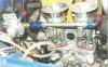
You will see from the photos that it all
fits neatly. I had the manifolds modified by Alfa II, which, as stated above, involves a
fair amount of work. I did do a little work on them myself before the definitive
installation, to allow some clearance for the throttle linkage, plus some minor dressing
just to make them look pretty. This is not to say that the work done is in any way bad, it
is just that I did a couple of cosmetic improvements that took a while to do, but I am
certain that you wouldn’t want to pay someone to do it. Whatever, part of doing
something like this is to see a nicely presented engine and all the little details give it
a more professional look, which you can be proud of.
The throttle cross-shaft was modified to suit, and sits correctly both for the carbs and
the throttle bodies. I chose short ram pipes for the throttle bodies on the basis that I
will have to have a filter on top of them, probably Pipercross or K&N, and I did not
want them fouling at the top. The throttle bodies have DCOE pattern flanges at the top
where the ram pipes sit, so my choice of filter will be dictated by that. The fuel rails
are the cast aluminum ones that Jenvey sell as part of the throttle body kit. I went for
the -6JIC threaded end connections, as that meant that connecting everything up was be
easier, as was fiddling about with it when I was trying to get things working properly. A
Malpassi adjustable fuel pressure regulator links onto the end of the fuel rail.
The lines that supply fuel from the front to rear, and the return to the tank are made
from 5/16th diameter copper ‘Bundy’ tubing. I soldered on -6JIC connections at
the front, then from the supply line is a feeder to a -6JIC end fitting high pressure fuel
filter located on the engine bay bulkhead in front of the passenger footwell. The feed
then goes from the filter through the fuel rails of the throttle bodies in series, then
into the regulator and back again to the return pipe, then on to the tank.
Onto all this has gone Mocal alloy re-useable end connectors and Aeroquip hosing, as this
is state of the art stuff. It also looks damned good too, of course, but it comes at a
price, I can assure you, and some may argue overkill. You will see from the photos what it
looks like, but there is also a schematic diagram with the different connections,
materials and units fitted.
I had previously had some doubts
concerning the routing of the return line. The non injection tank fitted to my car is not
rust (a miracle) so I wanted to keep it if at all possible. The trouble was that there was
no swirl pot in the tank, and the fuel return line was not positioned very well.
I got around this by plumbing the return line into the tank outlet line with a 'T' piece,
and routing the fuel supply to the pump into a high volume pump pre-filter. This acts as a
swirl pot and surge reservoir, and so far works fine.
Eventually, the fuel pressure will probably be set at around three bar, but exact values
will be determined by the rolling road session.
Wiring in the M3D unit
Fitting the injection was not as great a problem
as I had imagined it to be.
Emerald supplies you with the ECU, a lead to connect to a PC or laptop, an air temperature
sensor complete with connecting boot, a throttle potentiometer with the respective
connector, a floppy with the ECU programming software, a manual and a connector block
complete with all connecting pins and blanking grommets.
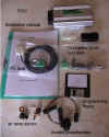
The complete M3d package
You will have to make up the loom yourself. It
sounds daunting, but anyone with a little experience of car electrics will be fine. To
what Emerald supplied, I added the following:-
Zetec coil unit complete with connector and some wire
6 metres 6mm (shrunk) dia heatshrink tubing
3 metres 10mm (shrunk) dia heatshrink tubing
3 metres 15mm (shrunk) dia heatshrink tubing
5 off 'injector' type connectors and boots
1 off three pin connector to suit the Bosch crank sensor
1 off three way male / female connecting block
1 off receptacle block to take one relay and three blade type fuses
1 off injection fuel pump
Crimp on spade connections, male and female, and eyelet type (4mm dia for pump
connections, 6mm dia for earthing connections)
15 metres red 1 sq.mm standard car wire
15 metres black 1 sq.mm standard car wire
10 metres each blue, brown, green, yellow, purple, green/yellow 1 sq.mm standard car wire
1 standard relay
assorted blade fuses, including a couple of 3 amp
You will also need:-
crimping pliers
wire strippers
wire cutters
hot air paint stripper (for heatshrink if used)
The Emerald M3D manual is not too difficult to follow, but there are some small
ambiguities that could do with some clarification. I will post individual diagrams for
each of the subsystems in order to make it easier.
One of the first things to decide is whether you
will be using conventional ignition or distributorless ignition. Refer to the ignition
section for more details.
You will then have to decide whether to go for
batched or sequential injection. I went for batched, being simpler, but left the
connections in place to enable an easy change at a later date.
The fuel pump has to be installed, complete with
a pre filter. The prefilter acts as a swirl pot as well as protecting the filter.
Obviously an earth wire is needed, and the +12 volt supply wire was routed through the car
to protect it. In the battery tray it was connected to a relay block that also has slots
for three blade fuses. The supply wire was connected so that it was switched live by the
relay when energised, and then passes through a fuse before going to the pump.
The switching circuit of the relay was connected
to +12 volts on one side, and the other terminal connected to the 'fuel pump relay driver'
connection of the ECU. In this way the relay earths via a switch in the ECU. When the ECU
detects engine rotation, the switch closes, actuating the relay and energising the pump.
Should the engine stop (an accident, for example) the pump is automatically cut.
The injectors are all fed with a +12 volt supply,
and again are earthed through a switched connection on the ECU. As I was making a batched
injector setup, it meant that I connected all four injectors in parallel, with all four
positive supplies coming together and all four negative connections coming together. The
injection connectors are a standard type, and use crimp on connectors. To determine which
is the positive terminal of the injector, just look at the plastic body of the connector;
there will be a '+' to indicate it. Also, remember to put the protective boot over the
wire before pushing the crimp connectors into their housing. The positive wires are all
then connected to the +12 volt switched supply, through one of the fuses on the relay
block. The negative connections are then connected to the 'Injector driver' connection of
the ECU.
The crank sensor is a little more tricky. I would
recommend that you make three individual connections for the wires, so that you can swap
them around until you get the ECU to recognise the sensor signal. There are six possible
combinations for connecting to the three relevant terminals of the ECU, and four of them
will not work. Of the two remaining combinations, both will work, but one will be correct
and the other not. however, to get you up and running, either will do, especially if you
are only using the injection.
The throttle potentiometer is simple, as the
colours are all referred to in the instruction manual. All you have to do is cut the right
length of wires, crimp the terminals on and push them into the receptacle.
The air and water temperature sensors are also
easy, sharing a common earth, with the remaining terminal being connected to the
respective pins on the ECU. The connector type is the same as the injectors, but there is
no need to get the wires to any particular terminals.
The ECU requires a good quality earth. Connect
this to or as near to the battery earth itself as you can.
I would recommend that the loom be manufactured
and installed in-situ, and that all the cable runs are sorted out there and then to ensure
that you don't end up with over long, or worse still, short cables.
Getting it all
working...
Once all this injection and
distributor-less ignition hardware had been fitted, I had to try to make it all work
together. I attempted to use the instructions that come with the EMS to get the engine
running.
The EMS came programmed with a basic,
safe fuel and ignition map from a similar sort of engine, perhaps from a 1.6 or 1.8 ford
Zetec. The engine did not want to run using this, point blank. After many hours of trying,
I decided to take a step back and simplify the system in order to attempt to diagnose why
it wouldn't run.
I had previously stated that I might run
into problems, and that as a contingency I could stick on the carbs and the distributor.
Well, that proved to be my saviour, or at least some of it did. I could not very easily
stick the carbs on because it would mean a change of fuel pump, plus devising a means of
attaching the throttle pot to the carbs. The distributor, however, could simply be bolted
back into place, and the connections remade by re-attaching the spade connectors. Refer to
the ignition section for more details.
This I did, and with the help of a can of 'Easy Start' and the lap top, we tried again.
Squirting the Easy Start in while cranking showed that the engine wanted to run. By
richening the mixture VERY considerably, it finally burst into life. It seems that the
fuel required by the engine was considerably more than he engine was getting using this
map and fuel pressure.
The original plan was that, since the
EMS can be reprogrammed using a laptop, I could play around to set everything to a
reasonable standard. I would then take the car down to Emerald Cams rolling road in south
London, and spend a day getting it set up perfectly. I would then drive it home with a big
happy smile on my face.
The reality was that we were having
problems getting the engine to run smoothly, especially at low speeds. This, plus some
other issues (water leaks from one of the inlet manifolds and the thermostat housing, plus
some massive toe in on the front suspension) delayed getting the car onto the road in
sufficient time to take it to Emerald for mapping.
What we did achieve, though, was to get
the car onto the road and start to at least find some approximate settings. Things did not
start well. For that matter, nor did the engine!
It was an absolute pig to start with.
Trying to pull away from a standstill would cause the engine to bog down, even using 4000
revs. Part of that was traced to the handbrake being adjusted too tight, with one of the
shoes hanging on. This was corrected, and things improved slightly.
To give you some idea, the little
cul-de-sac where we were starting from was 50 metres long, and we were starting from the
middle. It took 20 minutes of adjusting settings before we were able to make the 25 metres
to the end of the road....
Once we had the car pulling away from a
standstill ok, we started to go a bit further. This highlighted the massive toe-in that
the new suspension had endowed the car with. It simply did not want to turn. Very un-Alfa!
The toe in was improved by eye, and we could now take the car further afield. A nearby
industrial estate had some nice open roads, many of them dual carriageway, with virtually
zero traffic on it, and we headed for it.
Once there, we made rapid inroads in
roughly mapping the injection (no ignition yet, remember) and it got to be good enough
that we headed for a garage to get the tracking done properly. However, by this time we
had missed the chance to take the car to Emerald Cams for mapping. Such is life.....
A couple of problems surfaced during the
rough setting up that we were doing.
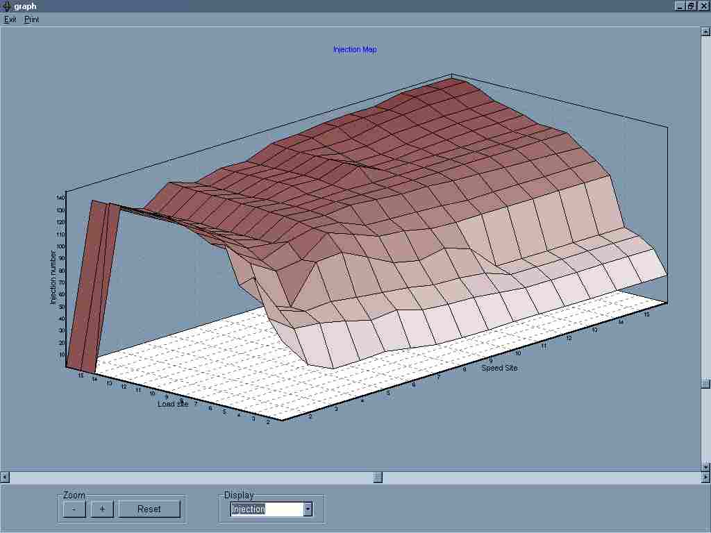
Firstly, it seemed that the fuel
pressure was way too low for the map that we had intended staring up with. As a result we
had to massively richen the fuel sites at the bottom end just to make it all work. The
resulting fuel map looks like a complete disaster area because of this, but it does enable
the car to run.
Secondly, as mentioned in the ignition
section, speed site 1 is non-existent due to the crank sensor output dropping below the
threshold that the ECU can read, so the ECU hunts between speed site 0 and 2 at idle.
Whenever the speed site was 0, the fuel pump is switched off as the ECU thinks the engine
is stopped. This means that the mixture has to be richened even more to cover the dead
moments when the fuel was cut. The emissions at idle were a country mile off, and a sub
1,000 rpm idle at the moment was not possible. When the car is taken for rolling road
mapping, this was sorted out read about that further on.
It was clear that without some
diagnostic equipment to help, just looking at one aspect of the fuel and ignition system
at a time was the way to go. When the engine didn't want to start, it was not possible to
determine whether the fuel or the ignition was wrong, so substituting one of those with a
known quantity allows you to concentrate on getting one parameter correct. You can then go
back and correct the other one.
Once we actually got the engine running,
it was a (relatively) short time between then and having the car in a condition where it
could be driven reasonably well. It was an enormous sense of achievement, too. It
was great even with a rough set of settings, and those 45mm rampipes make an addictive
noise....
Finally made it to
Emerald for the Rolling Road session
Well, the weeks and months went by and finally I
have had the chance to get the car down to Emerald Cams for tuning. For those of you that
didn't know, Emerald Cams is run by Dave Walker, who is actually the technical editor of
Car and Car Conversions magazine. Walkers Workshop is his bit.
Dave is straightforward guy, and it was fun to
help him and his business partner Carl do the car. They are good, but not pretentious, and
when the car was first strapped in, they immediately went to work on getting the crank
sensor problem sorted out. Carl is the electroncs guru, and within minutes spotted the
problem as two misplaced, or more correctly inverted, wires. Once fixed, the sensor
read correctly.
Dave elected to go straight for the
distributorless ignition system, rather than sort out two separate systems, so the first
job for me was to fit the Zetec coil unit on the special bracket I had made. I then wired
up the HT leads. The engine was then started up. Or rather, an attempt to get the engine
to run was made.
The bloody thing did not want to start at all,
just sitting coughing and spluttering. And so began the first of many 'lets find out what
wrong' sessions. First up, I called into question my placement of the ignition HT leads.
Maybe I had put leads for 1 & 2 on the positions for 3 & 4. Easily done. We
swapped, with no difference. Dave and Carl checked the software and found some small setup
discrepancies, but still the blasted thing didn't want to know. Come on, Les, what have
you done to it? We knew that the injection system functioned as the car had been driven
the 110 miles down there. So it must be the ignition.
Well, after a while, I was asked if I was certain
about the placement of the leads, and of course I said I was. After all, with a 1 - 3 - 2
- 4 firing order, the plugs for 1 and 2 go to the same coil. As the engine still wasn't
running, doubts about my logic were starting to get more solid. At that point we were
swapping leads just to check effects, but with a growing sense of embarassment I realised
that the problem may have been my fault after all.....
When I had initially used the Zetec coil, it had
been fitted in such a way that the HT lead outputs on the left hand side of the coil went
to the number 1 and 2 cylinders, and the right hand ones to 3 and 4. When I made up my
bracket, I had rotated the assembly by 90 degrees, so now the upper two outputs went
to cylinders 1 and 2 and the lower ones to 3 and 4.
Once I had swapped the leads, the engine now
'ran'. It ran like a pig, though. cylinders 2 and 4 seemed ok, but 1 and 3 weren't. As
they used different parts of the coil, it couln't be the coil unit. Now what?
Dave wanted to check the plugs, and with a sense
of foreboding realised that that task fell to me as I had been stupid enough to mention
what a bastard of a job they are to get at. Well, it had been a bastard before. Now, with
an engine that was sizzling hot after 1 hour in southern London traffic, it went miles
beyond being a bastard. Words cannot describe what an awful job this is. In addition, to
make things even worse, was the issue of plug leads. The rubber cap seals around the plug,
and to get them off requires a great deal of force, plus you have to pull them off
straight. Of course, hot engine, poor access, it isn't simple. That was to come back an
haunt me.
Eventually, after burning my hands an innumerable
number of times, I got the two plugs out. They were the Golden Lodge variety, and they
looked like someone had poured tar on them. In addition, Dave noted that the electrodes
didn't seem to be in the correct places, and finally a check by Carl showed that the
sparks were tracking internally rather than between the electrodes. Dave produced a set of
Nippondenso platinum tipped plugs, which are single electrode. They can run very large
gaps due to the design, which meant that they can ignite difficult mixtures.
Once fitted, the engine did finally run smoothly,
much to my relief.
The next issue was to get the slow running and
idle sorted out. Just like on carburettors, the throttle bodies had to be balanced, so
that each cylinder receives the same amount of fuel and air at idle. The old method was to
use a bit of tubing and listen to the noise made by each cylinder, but modern tooling
meant that a simple vacuum guage could be put onto each ram pipe to measure the volume of
air to each cylinder.
This actually resulted in more problems that I
had expected. The two throttle body units were well out with respect to each other, and
the crude boxer throttle linkage was not helping this. On carburettors this is not so
important as the carbs have an additional screw to fine tune this, but the throttle bodies
I had did not have this feature. Despite this, with some playing about with linkages and
the actuating rod lengths, we were able to get the bodies balanced, and the engine settled
down into a beautifully smooth sub 1000 rpm idle. We were making some headway.
Mapping of the injection and ignition started,
with low load mapping. This was uneventful, with the car being held at a certain rpm by
the rollers, and the throttle held at a certain load site. The process was repeated with
higher rpm and higher loads.
As the load increased, at higher rpm the engine
started to mis-fire, and shake violently. Something was wrong. In order to help diagnose,
the injector plugs were pulled off the injectors one by one. If the engine decreased in
rpm or ran rougher, obviously that particular cylinder was OK. The results showed that
cylinders 2 and 4 seemed more of a problem than the others, but not dramatically so. We
hadn't changed the plugs on those two cylinders, so that was something we could do.
On the number 4 plug, the lead is a real bitch to
get to. As I struggled with it, I was having difficulty getting the leverage necessary to
get a good grip on the plug rubber seal,but eventually got it free. I put the plug socket
in, and tried to get the plug off, but to no avail. For some reason I couldn't get the
socket on properly. A mirror was used to see what was going on, and showed that there was
a strange looking piece of metal on the end of the plug. Then it dawned on me; a quick
check down the end of the plug lead confirmed that the metal clip that secures onto the
end of the plug electrode had pulled out of the lead.
It took another 1/2 hour to get the stupid bit of
metal off the plug so that we could put it back onto the end of the lead and swap the
plug. The quality of the leads was not fantastic, and the way that the end connector was
crimped on was weak to say the least.
Finally the platinum tipped plugs were in and the
leads back on. Another attempt to run the engine under load showed that the engine still
mis-fired. Part of the problem seemed to be that unless the engine had a massive amount of
advance dialled in, it would run roughly. A lot of head scratching was going on, and all
connections were checked and then checked again. The timing of the engine was re-checked,
TDC and the trigger wheel timing reconfirmed, and the setup of the injection and ignition
program checked. We could not find anything wrong. Was the cam timing out? It didn't seem
to be otherwise the engine would not rev even with no load. What the hell was going on?
It was at this point that Carl made a discovery.
As the engine revved, he could hear the sparks. But how on earth could he hear the sparks
from inside the cylinder? Well, if they weren't actually in the cylinder he could hear
them, and if they weren't in the cylinder they couldn't be firing the mix, could they...?
The mirror was pressed into service once more, and if angled so that it showed the plug
and the plug cap, it revealed that the sparks were earthing directly from the end of the
plug cap to the head! No wonder the cylinders weren't firing!
Off came the lead again, and this time we found
the culprit straight away. In an attempt to stop the lead sealing cap from gripping on to
the plug too tightly, it had been moved beack, and the centre metal clip was exposed. As
the mix under pressure in the cylinder is more resistant to sparks than the ambient
atmosphere, it was easier for the sparks to jump from the end of the lead to the head.
Finally, the mystery of why the engine was running rough was solved. The leads caps were
corrected, and the engine behaved sweetly.
Dave then ran the engine up under load with no
mis-fire problems. He then started to finish off the mapping, but as the engine had not
been fully run in, he would not map under full load above 4500 rpm to protect the engine.
Once the engine was run in it could be re-checked for this portion of the rev-range.
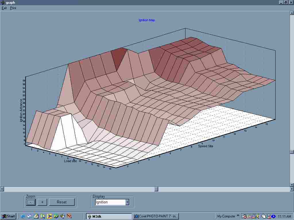 
Ignition
map
Injection
map
The above maps show the ignition timing and
injection fuelling maps respectively. These are tailored to exactly suit my engine in my
car. That is not to say that it would not suit another Alfa Boxer 16v engine, just that it
is the best possible at this moment for my particular engine. When the engine loosens up,
runs in, and more importantly stops using tons of oil, I will probably have to make small
adjustments to these maps to again suit the engine perfectly.
In addition, I am working on producing a pair of
heads with modified valves and ports, and possibly different cams. When installed, these
will require the maps resetting again to fine tune to the new requirements of the engine.
If this all sounds like you forever need to keep re-tuning, remember that that is only
what is needed with carburettors as well if you change heads and cams etc. The difference
is that carburettors are not as good at finding that extra few percent at high revs, but
more importantly the big differences at low to medium revs due to the mechanical
limitations of carburettors. This results in their not being too much discernable
difference, so few bother to go to the expense of trying. Injection changes that.
Ssssssssssmokin'..........
Unfortunately for me, my troubles were not fully
over. When I had got the engine running back at home, I had been a little surprised at how
much oil smoke was coming out of the exhaust. It wasn't run in, so I thought it would probably seal itself as the rings bedded in. As the tuning session continued, I was
dismayed to see more and more oil smoke from the exhaust. Dave suggested that the oil I
had put in, Castrol RS, was too good, and was not letting the engine bed in properly, and
that perhaps the bores had glazed. Due to the nature of the smoke though, it was unlikely.
To cut a long story short, the huge oil consumption I was seeing can mean only one of two
things, and those are either a head gasket problem or a broken piston ring.
I later rang the guys who had supplied the
reconditioned engine. They were very good about it, and didn't try to fob me off with any
excuses or anything. As the engine has only done 220 miles, thankfully the repairs to this
look like they will be done under warranty. That is the advantage of dealing with good
reputable companies, and my dealings with them on this has made sure that I will be happy
to deal with them again.
Back to the rolling road session, under power,
despite the smoke, the engine was really producing the power, and smoothly too. We
were unwilling to take the engine abouve 4500 rpm under load, for obvious reasons, but at
just under 4500 rpm, it was producing 97 bhp. That is not the whole story either, as the
power curve was just beginning a kink upwards at that point, promising more. Remembering
that a fully run in engine will be looser and therefore liberate more power, I can expect
that figure to increase to just over 100 bhp. What the peak bhp figure will be I don't yet
know, of course, but I will be anxious to get the car fixed, run in and back to find out.
Driving the car back home was a set of mixed
feelings. The car belched oil smoke out at idle, and was truly an embarrasment to drive in
traffic due to the clouds of smoke drifting away. On the other hand, when you put your
foot down, all thoughts of that disappeared. It goes, really goes, from any gear and any
speed, you put your foot down and it launches down the road. At the same time you have the
delicious boxer buzz and zing, and the growl from those big ram pipes. It is ballistic.
It also has made me take a closer look at the
brakes, as my instinct for self preservation was ringing some big bells in my head.
Despite repeatedly bleeding them, they just don't seem effective enough. If anyone reading
this has done anything to improve their 33 brakes, I want to hear it, please! In the mean
time, Nick Humphries of Nick Humphries Motorsport in Hinkley, Leicstershire, is going to
give the brake system a once over to make sure that there is nothing that I have missed.
|

