|
The
details referred to in the preceeding pages can be found here and on the other photo page
|
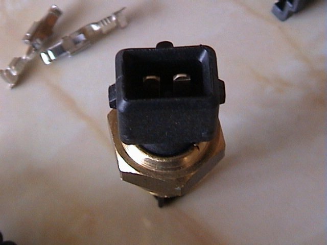
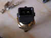
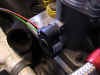
Air
temperature sensor
The air temperature sensor is supplied with the M3D package,
and should be mounted somewhere under the bonnet where it would measure the intake charge
temperature, but not where the induction airflow would artficially cool it.
The connection for the injectors and the
water temperature sensor is identical. |
|
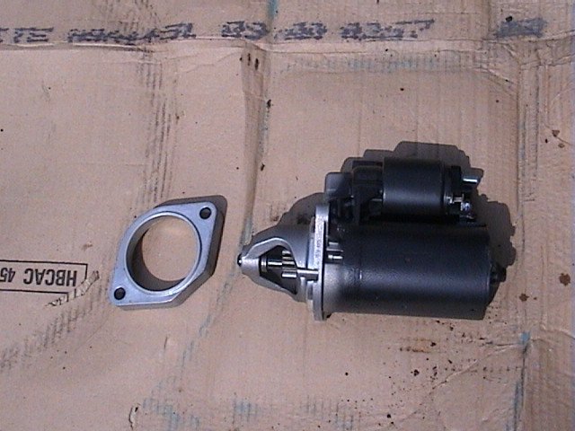
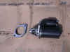
Starter
motor and spacer
The starter motor is the same as for the 8v unit, but needs a
spacer (seen here) to ensure that the starter gear engages with the flywheel ring gear. |
|
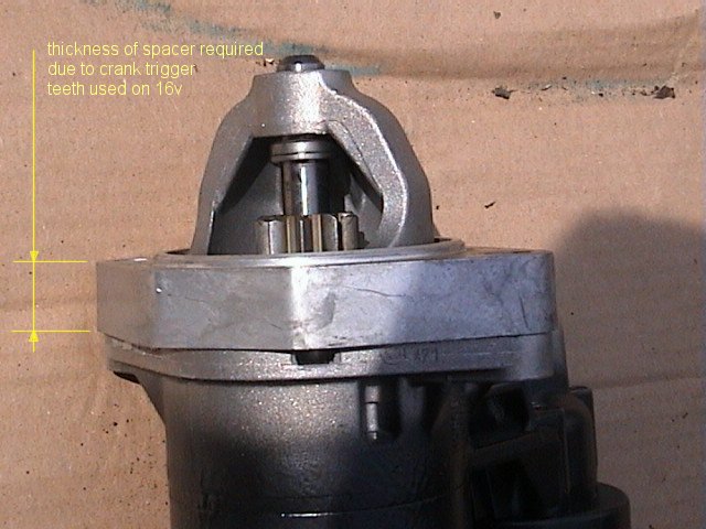
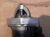
Starter
Spacer
The spacer is used to take account of the 60 - 2 teeth
crankshaft postition and speed indicator, used in conjunction with the crank position
sensor. |
|
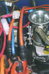
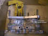
Throttle
linkage
The throttle bodies are supplied with a linkage that is best
suited to a side draught application, which required some 'L' shaped 90 degree adaptors to
be fabricated to allow use with the standard carburettor linkage. |
|
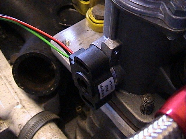
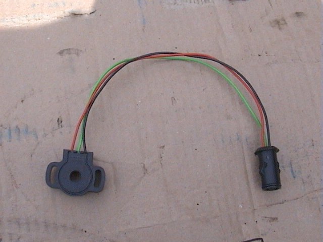
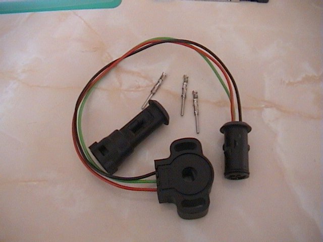
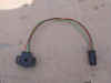
Throttle potentiometer
The throttle potentiometer was supplied with the M3D package, and fits directly
onto the end of the Jenvey throttle bodies with no modifications. Jenvey supply a fitting
kit as standard. |
|
The potentiometer must be
calibrated prior to the M3D injection and ignition mapping |
|
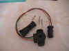
The kit received with the M3D unit comprises the
potentiometer, the female connector and the respective crimp-on pins |
|
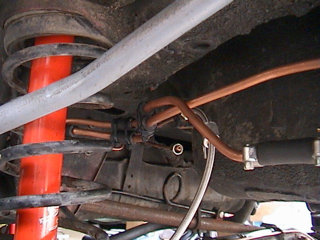
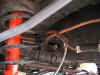
Rear solid fuel lines
The fuel lines at
the rear of the car were a mix of 8mm copper tube and high pressure fuel hose. A rigid low
pressure feed to, and high pressure delivery from, the pump were fabricated from the
copper tube in order to safely steer the fuel lines around the rear suspension. The ends
of the copper tube on the HP lines were flared slightly to ensure that the flexible fuel
hose was securely held. |
|
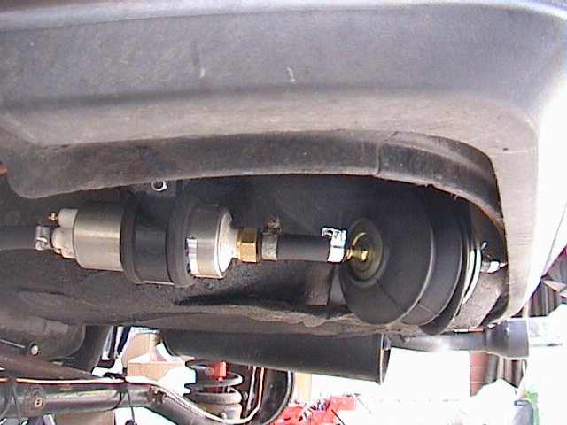
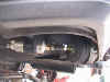
Fuel Pump and pre-filter
The fuel pump was mounted on the left hand side of the spare wheel well, in a
similar fashion to the fuel injected Alfa 33's. The low pressure pre-filter is mounted
directly behind it, but eventually this unit will be re-sited. The pump was flexibly
mounted to reduce transmitted vibration |
|
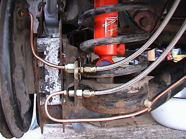
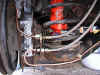
Rear brake
flexible hoses
I again copied the Alfa 33 setup for the rear flexible hose connections. Note the
use of Aeroquip hoses. |
|
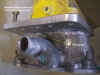
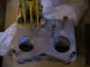
Inlet manifolds
You can see more or less how the inlet manifolds were
modified from these pictures. |
|
The existing injector
bosses will have to be blanked off, but not necessarily welded up like this. The M3D unit
has the capacity for multi-injector setups, where you could have two injectors per
cylinder. This gives benefits in low down torque and high speed power by giving a better
mixture presentation at all engine speeds. |
|
As the throttle bodies I was using have
the same flange pattern as the IDF series carburettors fitted to 8v engines, the mounting
flange of the manifolds were produced to suit this arrangement. In reality, any suitable
flange patern can be used. Depending on the flange pattern of the carb or throttle body
you wish to use, the flange plate is cut to suit. |
|